Kerf offset for whole outlines
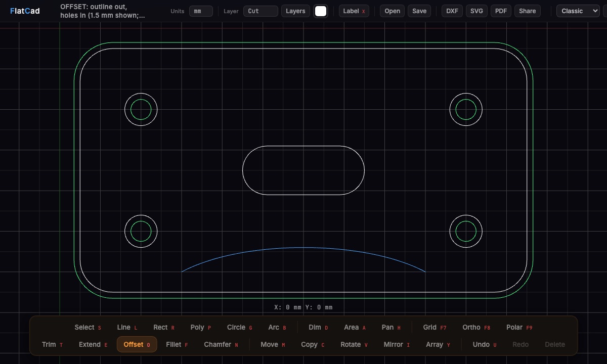
A laser burns away a thin strip of material, the kerf, so a part drawn at 50 mm comes out a little small and holes come out a little big. For press-fit joints, inlays and parts that have to fit, you offset the drawing by half the kerf first. FlatCad offsets the whole outline in one go, keeps arcs as arcs and trims the inside corners so the result is one clean closed shape.
1. Measure your kerf
Kerf depends on the machine, lens, power, speed and material, so measure it once for each material you use:
- Draw a 20 mm square and cut it out.
- Measure the square with calipers, say 19.84 mm.
- The kerf is the difference: 20 − 19.84 = 0.16 mm. You offset by half of that, 0.08 mm.
For a laser the kerf is often somewhere around 0.1–0.3 mm, but a test cut beats any rule of thumb.
2. Offset the outlines in FlatCad
Open your part: draw it, or open a DXF or SVG. Press O for Offset.
Click any edge of the outline. FlatCad picks up the whole outline of touching lines and arcs on that layer and highlights it. Hold Shift when clicking to offset a single segment instead.
Type half the kerf, for example
0.08, and press Enter. Arithmetic works too:0.16/2.Click the side to offset towards: outside the part for the outer contour, inside a hole for the hole. A preview follows the cursor.
For the next hole, click it and just press Enter: an empty entry repeats the last distance.
Delete the original outlines, or move them to the Guide layer, then export DXF or SVG.
Sharp or round corners?
Where an outline turns away from the offset side, the offset edges no longer meet. FlatCad closes the gap one of two ways, and J switches between them while you pick the side:
- Sharp (default): the edges are extended until they meet, like a CAD offset. Very pointed corners fall back to round so they don't shoot out.
- Round: an arc centred on the original corner. This is the exact path of the edge of the beam, and the most accurate kerf compensation.
Inside corners are always trimmed so the offset edges meet. At kerf sizes the difference between sharp and round is a fraction of a tenth of a millimetre.
What a whole-outline offset does that a simple one doesn't
| Offsetting segments one by one | FlatCad outline offset | |
|---|---|---|
| Corners | Gaps and overlaps to trim by hand | Trimmed and joined automatically |
| Arcs and fillets | Often turned into segments | Stay true arcs with the new radius |
| Radius smaller than the offset | Arc flips inside out | Collapses into a clean corner |
| Export | Loose pieces | One closed polyline per outline |
Starting from an SVG? Open it in FlatCad, offset it here, and export a DXF with the arcs intact.
Questions
How much should I offset?
Half the kerf. The beam removes material on both sides of the line, so a 0.16 mm kerf needs each outline moved 0.08 mm.
Which way does each outline go?
Outside contours of a part go outward and holes go inward, so the finished part keeps its drawn size. For a pocket or a slot that something must fit into, it's the other way round.
Doesn't LightBurn already do this?
LightBurn has a kerf offset setting in its cut settings, and that is the easiest route if LightBurn is your only software. Offset the geometry in FlatCad when the compensation has to be in the file itself: for a cutting service that cuts on the line, for other laser software, or to check the result before cutting.
What about a CNC router?
On a router the kerf is the bit diameter, and CAM software normally applies it with its own tool-radius offset. Offsetting the drawing is still useful for clearances, inlays and parts that must fit into each other.
What happens to a corner radius smaller than the offset?
When an inward offset is bigger than a rounded corner's radius, the arc disappears and the neighbouring edges meet in a sharp corner, which is what a real cutter would do.
Are the originals kept?
Yes. The offset outline is added next to the original. Delete the originals or move them to the Guide layer before exporting, so you don't cut both.